Description
Mechanical engineering is the discipline that applies engineering principles to design, analyze, manufacture, and maintain mechanical systems. This field represents a critical advancement in technological capability, enabling the systematic development of complex machines and mechanisms. Understanding mechanical engineering principles allows for the creation of increasingly sophisticated tools, machines, and structures that can perform work more efficiently and effectively.
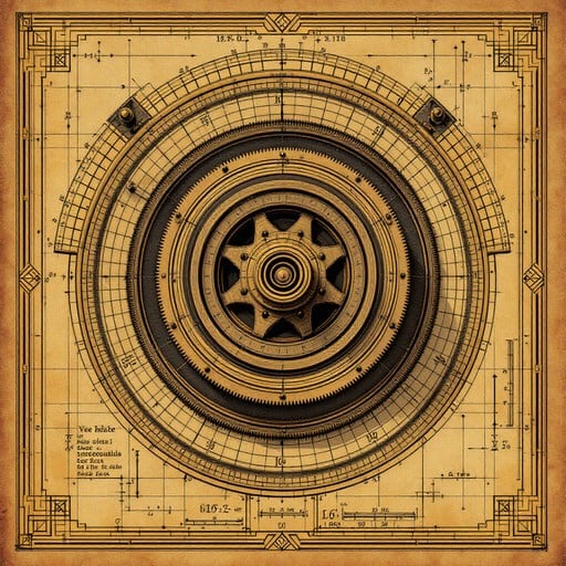
Historical engineering diagram showing a sophisticated pulley system design with precise geometric calculations
Practical Guide to Mechanical Engineering
1. Understanding Simple Machines
Simple machines are the fundamental building blocks of all mechanical systems. Mastering these principles allows for the creation of increasingly complex mechanisms.
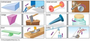
The six classical simple machines: lever, wheel and axle, pulley, inclined plane, wedge, and screw
A. The Lever
- Principle: A rigid bar that pivots on a fulcrum, used to multiply force or distance
- Classes of levers:
- First class: Fulcrum between effort and load (e.g., seesaw, crowbar)
- Second class: Load between fulcrum and effort (e.g., wheelbarrow, nutcracker)
- Third class: Effort between fulcrum and load (e.g., fishing rod, human arm)
- Practical construction:
- Select a strong, straight beam of wood or metal
- Create a stable fulcrum using a rounded stone, metal rod, or log
- Position the fulcrum according to desired mechanical advantage
- For precision levers, ensure the beam is uniform and balanced
- Reinforce contact points with metal plates to prevent wear
- Mechanical advantage calculation: MA = Distance from fulcrum to effort ÷ Distance from fulcrum to load
B. The Wheel and Axle
- Principle: A wheel attached to a central axle, allowing force applied to the wheel to be transferred to the axle at greater force but less distance
- Applications: Carts, water wheels, windlasses, steering mechanisms
- Practical construction:
- Create a circular wheel from wood, metal, or stone
- Ensure the wheel is balanced and has uniform weight distribution
- Craft a cylindrical axle from hardwood or metal
- Bore a precise center hole in the wheel to fit the axle
- Secure the wheel to the axle using pins, wedges, or adhesives
- Mount the assembly on bearings or in frame holes to allow rotation
- Lubricate contact points with animal fat, vegetable oil, or graphite
- Mechanical advantage calculation: MA = Radius of wheel ÷ Radius of axle
C. The Pulley
- Principle: A wheel with a grooved rim that holds a rope or cable, changing the direction of applied force
- Types of pulley systems:
- Fixed pulley: Changes direction but not force
- Movable pulley: Multiplies force but not direction
- Compound pulley: Combination of fixed and movable pulleys
- Block and tackle: Multiple pulleys arranged to multiply force
- Practical construction:
- Carve a wheel from hardwood with a U-shaped groove around the rim
- For metal pulleys, cast or forge a wheel with appropriate groove
- Create a central hole and insert a metal axle
- Mount the pulley in a frame or hook that can be attached to a support
- Use strong rope or cable that fits properly in the groove
- For compound systems, construct a frame to hold multiple pulleys
- Ensure all components can rotate freely with minimal friction
- Mechanical advantage calculation: MA = Number of rope segments supporting the load
D. The Inclined Plane
- Principle: A flat surface set at an angle to the horizontal, reducing the force needed to raise an object
- Applications: Ramps, roads on hillsides, loading platforms
- Practical construction:
- Select a strong, flat board or surface material
- Ensure the surface is smooth to minimize friction
- Create a stable support structure at the desired angle
- For permanent installations, secure the plane to prevent shifting
- Add side guards for safety when moving objects
- For heavy loads, reinforce the plane with cross-supports
- Mechanical advantage calculation: MA = Length of slope ÷ Height of slope
E. The Wedge
- Principle: A portable inclined plane that converts force applied to its blunt end into forces perpendicular to its sloping sides
- Applications: Axes, knives, chisels, doorstops, splitting logs
- Practical construction:
- Select dense, hard material (wood, stone, or metal)
- Shape the material into a triangular form
- Create a wide blunt end for receiving force
- Form a sharp edge or point at the opposite end
- For metal wedges, forge to shape and then harden
- For wooden wedges, select grain direction for maximum strength
- Maintain the edge with regular sharpening
- Mechanical advantage calculation: MA = Length of wedge ÷ Width of thick end
F. The Screw
- Principle: An inclined plane wrapped around a cylinder, converting rotational motion to linear motion
- Applications: Fasteners, clamps, presses, jacks, drills
- Practical construction:
- Begin with a cylindrical rod of wood or metal
- Mark a spiral line around the cylinder at consistent angle
- For wooden screws, carve along the spiral line to create threads
- For metal screws, use a lathe or thread-cutting tools
- Create a matching threaded hole or nut
- For large screws, add a handle or lever for turning
- Lubricate threads to reduce friction
- Mechanical advantage calculation: MA = 2π × Radius of handle ÷ Pitch of screw
2. Compound Machines and Mechanisms
Compound machines combine two or more simple machines to perform more complex tasks. Understanding how to integrate simple machines is essential for advanced mechanical engineering.
A. Gears and Gear Trains
- Principle: Toothed wheels that mesh together to transmit rotation and torque
- Types of gears:
- Spur gears: Straight teeth parallel to axis of rotation
- Bevel gears: Conical wheels with teeth for perpendicular shafts
- Worm gears: Screw-like gear meshing with a toothed wheel
- Rack and pinion: Converts rotary motion to linear motion
- Practical construction:
- Create a circular blank from hardwood or metal
- Mark the circumference into equal divisions for teeth
- Cut teeth using saws, files, or specialized gear cutters
- Ensure teeth have proper profile for smooth meshing
- Bore center hole for mounting on shaft
- For wooden gears, reinforce teeth with metal inserts if needed
- Mount gears on parallel shafts at proper distance
- Lubricate contact points to reduce wear
- Gear ratio calculation: Ratio = Number of teeth on driven gear ÷ Number of teeth on driver gear
B. Cams and Followers
- Principle: A rotating or sliding piece that transforms rotary motion into reciprocating motion
- Types of cams:
- Disc cam: Circular disc with offset profile
- Cylindrical cam: Groove cut into a cylinder
- Linear cam: Sliding piece with angled surface
- Practical construction:
- Design the cam profile based on desired motion pattern
- Create a template of the profile on paper
- Transfer the profile to wood or metal blank
- Cut and shape the cam according to the profile
- Smooth all edges to reduce friction
- Create a follower with appropriate contact surface
- Mount cam on rotating shaft and follower on guide
- Add spring tension to keep follower in contact with cam
C. Linkages
- Principle: Connected rigid bodies designed to transform one type of motion into another
- Common linkage types:
- Four-bar linkage: Four links connected by pivots
- Slider-crank: Converts rotary motion to reciprocating motion
- Scotch yoke: Creates pure sinusoidal motion
- Pantograph: Used for copying or scaling motion
- Practical construction:
- Design the linkage on paper, determining link lengths
- Create links from wood, metal, or other rigid material
- Drill precise pivot holes at required positions
- Connect links using pins, rivets, or bolts
- Ensure all joints can rotate freely with minimal play
- Mount the assembly on a stable base
- Lubricate all pivot points
- Test and adjust for smooth operation
3. Power Transmission Systems
Power transmission systems transfer mechanical energy from a source to where it's needed, often changing speed, torque, or direction in the process.
A. Belt and Pulley Systems
- Principle: Flexible belts running over pulleys to transmit power between shafts
- Types of belt drives:
- Flat belt: Simple band running over cylindrical pulleys
- V-belt: Belt with V-shaped cross-section running in grooved pulleys
- Round belt: Circular cross-section belt in grooved pulleys
- Crossed belt: For reversing direction of rotation
- Practical construction:
- Create pulleys from wood or metal with appropriate profile
- For flat belts, ensure pulley surface is slightly crowned
- For V-belts, create accurate V-grooves in pulleys
- Make belts from leather, rope, or woven fabric
- Join belt ends by stitching, lacing, or using metal fasteners
- Mount pulleys on parallel shafts at appropriate distance
- Include tensioning mechanism to maintain proper belt tightness
- Align pulleys carefully to prevent belt walking off
- Speed ratio calculation: Ratio = Diameter of driver pulley ÷ Diameter of driven pulley
B. Chain and Sprocket Systems
- Principle: Metal chain engaging with toothed wheels (sprockets) to transmit power
- Advantages over belt systems:
- No slippage, maintaining exact speed ratio
- Can transmit higher torque
- Less affected by environmental conditions
- Can operate in compact spaces
- Practical construction:
- Forge or cast sprockets with teeth designed for chain pitch
- Create chain links from metal plates and pins
- Assemble chain by connecting links with pins
- Mount sprockets on shafts with keys or set screws
- Install chain around sprockets with proper tension
- Include adjustment mechanism for chain tension
- Provide lubrication system for chain and sprockets
- Add guard to contain broken chain in case of failure
C. Shaft Couplings and Joints
- Principle: Devices that connect shafts for transmitting power while accommodating misalignment or allowing articulation
- Types of couplings:
- Rigid coupling: For perfectly aligned shafts
- Flexible coupling: Allows slight misalignment
- Universal joint: Permits angular movement between shafts
- Clutch: Allows engagement/disengagement of power transmission
- Practical construction:
- For rigid couplings, create flanged discs that bolt together
- For flexible couplings, use leather or rubber inserts between metal parts
- For universal joints, forge cross-shaped center piece with bearing cups
- Ensure precise machining of all components
- Create keyways or splines for torque transmission
- Balance rotating components to prevent vibration
- Provide adequate lubrication for moving parts
- Include locking mechanisms to prevent loosening
4. Bearings and Supports
Bearings support rotating or sliding components, reducing friction and wear while maintaining alignment.
A. Plain Bearings
- Principle: Simple bearing surfaces that support loads through sliding contact
- Types of plain bearings:
- Journal bearing: Cylindrical bearing supporting radial loads
- Thrust bearing: Flat surfaces supporting axial loads
- Guide bearing: Supports sliding motion along a path
- Practical construction:
- Select bearing material based on load and speed (wood, bronze, brass)
- For wooden bearings, use dense hardwoods with grain perpendicular to shaft
- For metal bearings, cast or machine to precise dimensions
- Create oil grooves or reservoirs for lubrication
- Ensure proper clearance between shaft and bearing
- Split bearings into halves for easier installation
- Include adjustment mechanism for wear compensation
- Provide seals to keep lubricant in and contaminants out
B. Rolling Element Bearings
- Principle: Bearings that use balls or rollers between races to reduce friction
- Types of rolling bearings:
- Ball bearings: Spherical rolling elements
- Roller bearings: Cylindrical, tapered, or spherical rollers
- Needle bearings: Thin cylindrical rollers
- Practical construction:
- Forge or machine inner and outer races with proper profiles
- Create rolling elements (balls or rollers) from hardened steel
- Fabricate cage to maintain spacing between rolling elements
- Assemble components with precise clearances
- Pack with appropriate lubricant
- Install seals or shields to protect internal components
- Mount on shaft and in housing with proper fit
- Avoid over-tightening which can cause premature failure
C. Pivot and Fulcrum Designs
- Principle: Points or edges that support rotating or rocking motion
- Common applications:
- Balance scales
- Compass needles
- Door hinges
- Lever fulcrums
- Practical construction:
- For knife-edge pivots, forge hardened steel edges
- For point pivots, create hardened conical points
- Make matching surfaces from hardened material
- Ensure precise alignment of pivot components
- Provide adjustment mechanism for wear compensation
- Include lubrication method appropriate for application
- Protect from contamination and damage
5. Mechanical Design Principles
Effective mechanical design requires understanding fundamental principles that govern how components interact and perform.
A. Force Analysis and Balance
- Static equilibrium: Sum of forces and moments equals zero
- Force diagrams:
- Identify all forces acting on a component
- Represent forces as arrows showing direction and magnitude
- Resolve forces into components along coordinate axes
- Sum forces in each direction to check balance
- Moment calculations:
- Identify pivot points or axes of rotation
- Calculate moment as force × perpendicular distance
- Sum clockwise and counterclockwise moments
- Adjust design to achieve balance if needed
B. Material Selection and Strength
- Material properties to consider:
- Strength: Ability to withstand forces without failure
- Stiffness: Resistance to deformation under load
- Hardness: Resistance to surface indentation
- Toughness: Ability to absorb energy without fracturing
- Wear resistance: Ability to withstand surface abrasion
- Common materials and applications:
- Hardwoods: Frames, levers, wheels, gears
- Cast iron: Heavy frames, gears, cylinders
- Wrought iron: Shafts, linkages, fasteners
- Steel: High-stress components, springs, cutting tools
- Bronze/brass: Bearings, bushings, gears
- Leather: Belts, seals, flexible connections
- Safety factors:
- Design components to withstand several times expected load
- Use higher safety factors for critical components
- Consider dynamic loads and fatigue in calculations
- Account for material variations and imperfections
C. Friction and Efficiency
- Understanding friction:
- Static friction: Resistance to initial motion
- Kinetic friction: Resistance during motion
- Rolling friction: Resistance to rolling motion
- Friction reduction methods:
- Lubrication: Apply oils, greases, or solid lubricants
- Surface finishing: Polish contact surfaces
- Material pairing: Select compatible materials
- Rolling elements: Replace sliding with rolling
- Alignment: Ensure proper component alignment
- Efficiency calculations:
- Efficiency = Output power ÷ Input power × 100%
- Account for all sources of power loss
- Measure input and output to determine actual efficiency
- Improve design to minimize losses
Troubleshooting Common Issues
Excessive Friction and Binding
Cause: Misalignment, inadequate clearance, poor surface finish, lack of lubrication
Solution: Check and correct alignment, increase clearances where needed, improve surface finish, apply appropriate lubricant
Premature Wear
Cause: Improper material selection, excessive loads, contamination, inadequate lubrication
Solution: Select more wear-resistant materials, reduce loads or increase component size, improve sealing, establish regular lubrication schedule
Vibration and Noise
Cause: Imbalance, misalignment, loose components, resonance, worn bearings
Solution: Balance rotating parts, align components precisely, tighten fasteners, change operating speed to avoid resonance, replace worn bearings
Mechanical Failure
Cause: Overloading, fatigue, improper heat treatment, material defects
Solution: Redesign for higher strength, reduce stress concentrations, improve heat treatment process, inspect materials before use
Power Loss
Cause: Excessive friction, slipping belts or clutches, misalignment, component binding
Solution: Reduce friction through better design and lubrication, tension belts properly, align components, ensure free movement of all parts